Morley Pro Series II wah mods and measurements
 Folks
seem to have mixed opinions of Morley wah pedals. I wanted to by a
second hand wah pedal and thought a Morley with it´s optical system
would be a good choice (no scratchy pot to replace).
Folks
seem to have mixed opinions of Morley wah pedals. I wanted to by a
second hand wah pedal and thought a Morley with it´s optical system
would be a good choice (no scratchy pot to replace).
When I got this Pro Series II, I was impressed by it´s rugged
construction. Unfortunately I was less happy when I played through it.
Everything happened at the first half of pedal movement, rest had no
effect at all. That made it very difficult to use. Just a slight move
shifted the resonance too much.
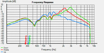
To find out what´s going on, I hooked the pedal to a computer to
measure frequency response at different pedal positions. Blue curve
shows the response pedal up, red in the middle and light green pedal
down.
The dark green curve shows the response at pedal totally up. It
seems that the effect "goes on" only after the pedal has moved
slightly. I don´t know if this is intentional, but I like it this way.
The peak at pedal down is much too high at 3 kHz. For many other wah pedals this frequency is 1600 - 2200 Hz.
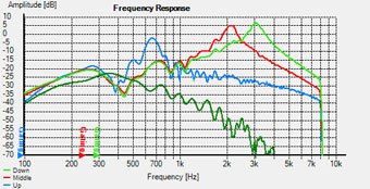
Original curves
The usual way to solve this problem is to bend the led (that illuminates the ldr) a little up or down.
I thought a better solution would be to add a potentiometer in series with the led. That should work as a range -control.
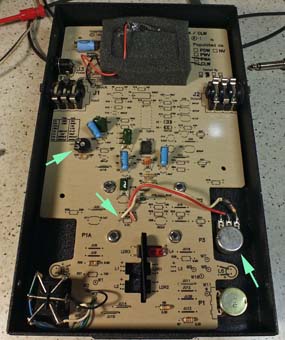
So I removed resistor R28 (the series resistor for led L4) and
installed a 10k lin potentiometer with the original 4k7 resistor in
series.
This range adjustment works as expected and I´m quite happy with it.
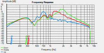
Below are frequency plots after modification. Range pot fully counter-clockwise (left) and fully clockwise (right).
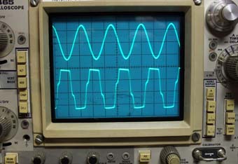 Another
problem: when testing the pedal, I heard some nasty distortion. Also,
the sound was much louder with effect on compared to bypass (even with
level pot at minimum).
Another
problem: when testing the pedal, I heard some nasty distortion. Also,
the sound was much louder with effect on compared to bypass (even with
level pot at minimum).
I fed a test signal from audio generator to the pedal (1,5V p-p) and
connected output to my oscilloscope. As you can see, the output signal
was badly clipped. I went through the circuit, but couldn´t find any
fault.
First, I tried to reduce gain of the filter op amp by replacing
feedback resistor with a trim pot. That didn´t work. Ok, I could reduce
the gain, but that also reduced the filter´s Q too much.
Then I replaced series resistor R1 (39k) with a 100k trim pot and that
did the trick. I set the level pot at middle position and adjusted the
trimmer until the output level was same for bypass and effected signal.
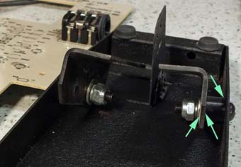 The last annoyance was pedal´s sticky action. Obviously some lubrication was needed.
I took the whole thing apart and put little crease to places shown in the picture. Job done.
All this tinkering took a while, but now the pedal works as I think it should.
A schematic diagram can be found here:
http://morleypedals.com/downloads.html
Big thanks to Morley for making documentation available.
©Jukka Korppi 2016